GraphAbs
Create: Simple series circuit
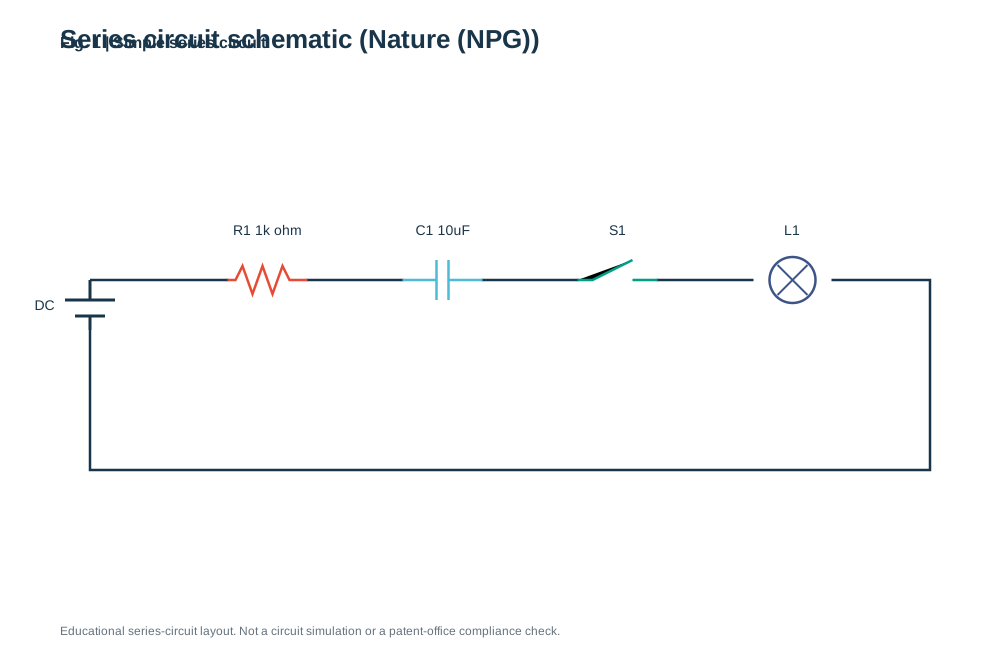
Create a simple series schematic using resistor, capacitor, switch and lamp rows. This is an educational drawing tool; it does not simulate the circuit or verify patent drawing requirements.
)%22%3E%3Crect%20width%3D%22100%25%22%20height%3D%22100%25%22%20fill%3D%22white%22%2F%3E%3Cstyle%3Etext%7Bfont-family%3AArial%2C%20Helvetica%2C%20sans-serif%3Bfill%3A%2319354a%7D.tick%7Bfont-size%3A14px%7D.label%7Bfont-size%3A17px%7D.small%7Bfont-size%3A12px%3Bfill%3A%2365717d%7D%3C%2Fstyle%3E%3Ctext%20x%3D%2260%22%20y%3D%2248%22%20font-size%3D%2226%22%20font-weight%3D%22700%22%3ESeries%20circuit%20schematic%20(Nature%20(NPG))%3C%2Ftext%3E%3Cpath%20d%3D%22M90%20280H930V470H90V330%22%20fill%3D%22none%22%20stroke%3D%22%2319354a%22%20stroke-width%3D%222.5%22%2F%3E%3Cpath%20d%3D%22M65%20300H115M75%20316H105M90%20280V300M90%20316V330%22%20stroke%3D%22%2319354a%22%20stroke-width%3D%223%22%2F%3E%3Ctext%20class%3D%22tick%22%20x%3D%2245%22%20y%3D%22310%22%20text-anchor%3D%22middle%22%3EDC%3C%2Ftext%3E%3Crect%20x%3D%22228.5%22%20y%3D%22264%22%20width%3D%2278%22%20height%3D%2232%22%20fill%3D%22white%22%2F%3E%3Cpath%20d%3D%22M227.5%20280h8l7-14%2010%2028%2010-28%2010%2028%2010-28%207%2014h18%22%20fill%3D%22none%22%20stroke%3D%22%23E64B35%22%20stroke-width%3D%222.5%22%2F%3E%3Ctext%20class%3D%22tick%22%20x%3D%22267.5%22%20y%3D%22235%22%20text-anchor%3D%22middle%22%3ER1%201k%20ohm%3C%2Ftext%3E%3Crect%20x%3D%22403.5%22%20y%3D%22264%22%20width%3D%2278%22%20height%3D%2232%22%20fill%3D%22white%22%2F%3E%3Cpath%20d%3D%22M402.5%20280h34m0-20v40m12-40v40m0-20h34%22%20stroke%3D%22%234DBBD5%22%20stroke-width%3D%222.5%22%2F%3E%3Ctext%20class%3D%22tick%22%20x%3D%22442.5%22%20y%3D%22235%22%20text-anchor%3D%22middle%22%3EC1%2010uF%3C%2Ftext%3E%3Crect%20x%3D%22578.5%22%20y%3D%22264%22%20width%3D%2278%22%20height%3D%2232%22%20fill%3D%22white%22%2F%3E%3Cpath%20d%3D%22M577.5%20280h15l40-20m0%2020h25%22%20stroke%3D%22%2300A087%22%20stroke-width%3D%222.5%22%2F%3E%3Ctext%20class%3D%22tick%22%20x%3D%22617.5%22%20y%3D%22235%22%20text-anchor%3D%22middle%22%3ES1%3C%2Ftext%3E%3Crect%20x%3D%22753.5%22%20y%3D%22264%22%20width%3D%2278%22%20height%3D%2232%22%20fill%3D%22white%22%2F%3E%3Ccircle%20cx%3D%22792.5%22%20cy%3D%22280%22%20r%3D%2223%22%20fill%3D%22white%22%20stroke%3D%22%233C5488%22%20stroke-width%3D%222.5%22%2F%3E%3Cpath%20d%3D%22M777.5%20265l30%2030m-30%200%2030-30%22%20stroke%3D%22%233C5488%22%20stroke-width%3D%222%22%2F%3E%3Ctext%20class%3D%22tick%22%20x%3D%22792.5%22%20y%3D%22235%22%20text-anchor%3D%22middle%22%3EL1%3C%2Ftext%3E%3Ctext%20x%3D%2260%22%20y%3D%22635%22%20class%3D%22small%22%3EEducational%20series-circuit%20layout.%20Not%20a%20circuit%20simulation%20or%20a%20patent-office%20compliance%20check.%3C%2Ftext%3E%3C%2Fsvg%3E)
1. What is Simple series circuit?
Scientific definition and academic background
A clean series circuit schematic depicts resistors, capacitors, switches, and loads with crisp black-and-white linework suitable for engineering methods sections and educational diagrams.
Trace the wires as continuous paths and identify each component by its symbol and reference label.
2. Key Visual Anatomy & Elements
Deconstruction of axes, visual geometries, and annotations
Standard Component Symbols
Distinct schematic symbols for resistor, capacitor, switch, and lamp elements.
Reference Designators
Clean R1, C1, S1 designators and component values next to each symbol.
Orthogonal Routing
Crisp right-angle wiring keeps circuit connectivity unambiguous.
3. Required Data Schema & Formatting
Column definitions, value constraints, and data specifications
| Column | Type | Example | Role & Meaning | Required |
|---|---|---|---|---|
| Type | Enum | resistor / capacitor / switch / lamp | Schematic component type | Required |
| Label | String | R1 1k ohm | Reference designator and value | Required |
Data Note: Define one series component per row using resistor, capacitor, switch, or lamp. Intended for clean educational schematics rather than circuit simulation.
4. Real Publication Sample Dataset
Copy sample data or load directly into the workspace above
Type,Label
resistor,R1 1k ohm
capacitor,C1 10uF
switch,S1
lamp,L1
5. Scientific Insights & Publication Legend
Hypothesis addressed and a ready-to-use Nature/Cell figure legend template
Core Scientific Question:
How are the key passive and switching components arranged in the experimental test loop?
Interpretation Guide:
A crisp vector schematic lets readers verify hardware wiring and component values at a glance.
Standard Journal Figure Legend Template:
6. Peer Review Solutions & Pitfall Prevention
Overcoming reviewer critiques and eliminating common desk-rejection traps
Reviewer notes: "The benchtop photo is cluttered; include a clean circuit schematic."
Renders crisp monochrome vector SVG linework ready to pair with benchtop photos.
7. Reviewer Checklist & Journal Formatting Specs
Four indispensable pre-submission quality checks to ensure seamless editorial pass
Column Width
Single column (89 mm)
Typography
Arial / Helvetica 7–8 pt
Palettes
Pure black linework on white background
Resolution
Vector SVG/PDF or 600 DPI monochrome line art
Scope note
This page is for basic circuit communication. It does not provide patent-compliant drawings, legal advice, or assurance that a filing will be accepted.